|
An attempt to get this more complete March 2, 2023
Much of what is here is dated information, my first goal is to get this page working in its new location on my website. Text and pictures will first to make functional in the one link. Next will be to add content. Wish me luck. Please, if you have information you feel would assist in this, or comments about the content etc, please post something on the Impala SS Forum in the thread linked right below. https://www.impalassforum.com/threads/z28-cluster-mod-instructions.1283449/
-------------------------------------------- Some old, some updated, all is a work in progress --------------------------------------- DATED INFO: July 18, 2015 I have found a document here that was in a set of my notes. I have copied it in at the bottom of this page. I also found two wiring diagrams I did, they are linked here:
July 15, 2015 I am going to try to update some of this info based on memory... a dangerous thing for this old retired gearhead... and from any current source I can find. I have pictures of mods I made to the Z28 cluster I purchased in 2004, and this partially complete wiring info. The info below is ( I believe ) mostly correct for a '95 Bbody, I need to verify what I said below in 2006. Ugh. I have found Bob's website to have moved again and he has some great info HERE. I have just sent him an email and will hopefully be able to collaborate a bit with him and perhaps Gary Meier if I can get current contact info. I just want to include a few more correct pieces of information here since this is such a great 'old mod! -Gerry
These are some wiring diagrams I have been sent while putting a Z28 Cluster in my 96 Impala SS Hopefully they will help you as much as they did me. Thanks to Keith and Chad for all' there help, pointers, links, pictures, etc.... and to Bob Lane for the BIGGEST site covering this... 9C1 dot come and to Kevin Alexander for having the patience to make an adapter harness, modify clusters and sell them as a kit!! If you find yourself wanting to make your own harness, you need to snag some connectors from the wiring harness going to the ECM of a 90 series Beretta or Corsica. It takes this connector from TWO cars to have enough pins to fill all the needed wires in the z28 cluster. For the Impala end, you can desolder the connectors from old Capricedigital clusters. Ed Runnion and Tully Gould shared this tidbit with me. I need to find the time to go boneyard shopping, just to get a set. You might find a 94-97 Camaro with a harness AND connector from a boneyard too.
Some of these are LARGE sizes, so be patient.... The pinout cross reference The only issue on my 96 was the oil pressure wire. I had to use the f-body sending unit ( no surprise) but on the 96 with Kevin's harness, I had to add a wire from pin B8 on connector C1 at the Impala end to pin C2 at the Camaro end to get it to work.... I have given this feedback to Kevin, hopefully now some of the 96 mystery is solved.... The other issue to get the gauge working absolutely accurate is to bypass or wire around the 60 ohm resistor that is in the harness between the sending unit and the dash connector. Its in the harness just above the ventilation controls. I should go back in there or post some pictures on the next one we do.... I have recently discovered this wiring table is not accurate for a '96 Impala. I will assume it is accurate for 94-95, since there is a difference in the cluster. As of April 22, 2006, I will attempt to resolve the inaccuracies and post new info for the '96. -Gerry You can also find similar information and other information about this conversion here on the Region Of Doom Impala Club, but it is no longer in existence. (gm 3/2/23)
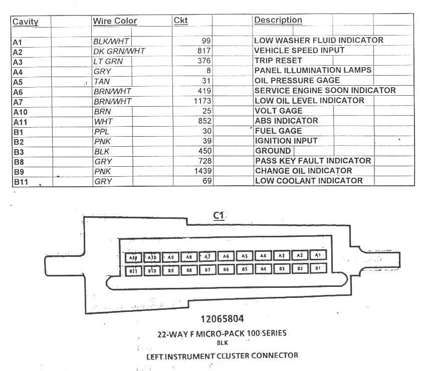
The C1 connector ( left side of steering colum )
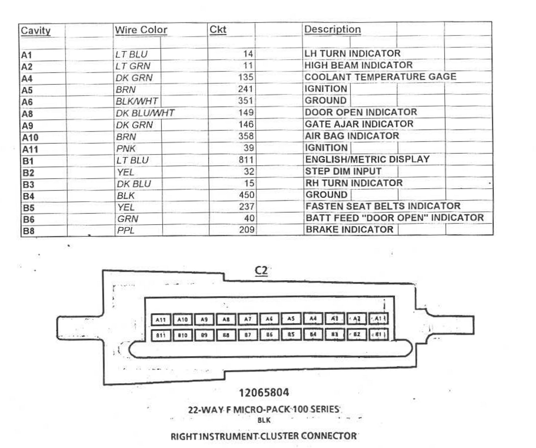
The C2 connector ( right side of steering column )
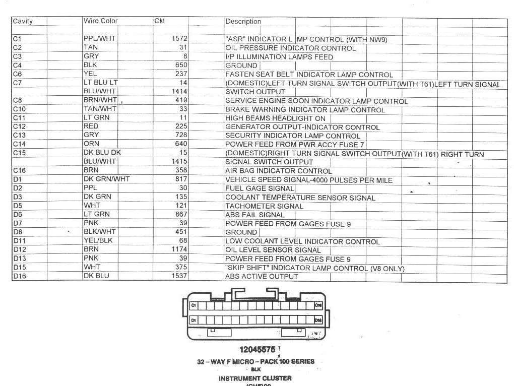
And the Z28 Instrument cluster pin out
July 18, 2015 Source of this document is unknown at the moment. If you recognize it please contact me so I can link the correct attribution ===============================================================
Basic 94-96 Camaro Cluster Modifications
All descriptions are based on viewing the back of the Camaro gauge cluster with the female cluster connector at the right and the black plasticcircuit board cover removed.
View this (link invalid) page to familiarize yourself with the layout of the circuit board and the location of the solder pads used in performing this modification.
ABS INOP & LOW OIL Light Circuits To enable the ABS & LOW OIL lights to function correctly in a 94-96 B-Body, the ABS inverter circuit and the LOW OIL logic built in to the Camaro cluster must be by-passed. This involves cutting 2 traces and installing 2 jumper wires.
Cutting Traces An Exacto knife, with its very sharp point, is an excellent tool for removing a section of a trace. How much to remove? Cut 2 lines in the trace, approximately 1/16" apart. Remove all traces of solder between the the lines with your Exacto knife.
Remove the bulb (if installed) from the ASR socket, the LH bulb of the three along the very bottom of the circuit board. See circuit board (link invalid). Follow the arrows to the 2nd solder pad and remove a very small section of the trace in the spot indicated in the graphic. The ABS inverter circuit has now been by-passed. Referring to the very LH side of the circuit board (link invalid) remove a section of the trace in the spot indicated. The LOW OIL logic circuit has now been by-passed.
Installing Jumper Wires
WARNING: It is strongly recommended that this part of the modification be performed by someone who has the correct tools and supplies and is an expert in modifying circuit boards. If you have the slightest doubt as to your abilities, do not attempt to add these jumper wires to your board! One mistake and youll be buying another Camaro gauge cluster. Proceed only at your own risk and expense!
View this (link invalid) page for a general idea of the routing of the jumper wires and for an expanded view of the female cluster connector solder pads.
Remove the bulb (if installed) from the ABS INOP socket, the RH bulb of the three along the very bottom of the circuit board. See (link invalid). Indicated by an arrow, a solder pad is located directly to the left of this socket. Solder one end of a length of wire to this pad and the other end to the solder pad at the female cluster connector terminal D6. The ABS INOP light will now function correctly.
Note the position of the Coolant Temperature gauge in the front of the cluster. Refer to the same general area on the circuit board (link invalid) An arrow points to a solder pad. Solder one end of a length of wire to this pad and the other end to the solder pad at the female cluster connector D12. The LOW OIL light will now function correctly.
Changing The Odometer Mileage Changing the Camaro cluster odometer to agree with your vehicles actual mileage will require removal of the circuit board from the cluster housing. Then remove the odometer/trip indicator from the housing. Changing the odometer is a Rubiks Cube process. It took me 2 days to understand it with help from (link invalid) Ill try to explain the process (link invalid).
Notes If you are using F-Body PCM programming, the LOW OIL circuit modification is not required. Remove Skip Shift, Low Trac, and ASR bulbs. They are not used in a B-Body installation.
gem 03/02/2023 10:41 AM |
|||