|
PCM Programming Harness Pease feel free to let me know if you have questions, or if you have comments!
I had always wanted some method of programming OBD-1 and OBD-2 PCMs for our Impala SS Club vehicles that removed the risk of having bad battery connections or low batteries 'fry' flash modules in PCMs. This had happened to us on a recent Dyno Day while Bryan Herter of PCMForless was tuning some of our vehicles with our favorite tuning software TunerCat ! TC is VERY responsive to the LT1 community and many others!
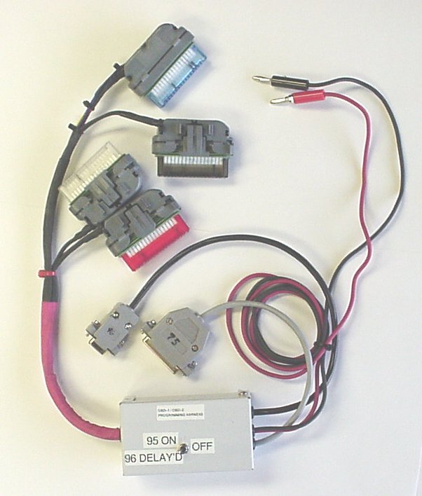
Here is a short write up and picture showing this cabling 'rig'
The power supply which feeds
this must be no lower than 12.5 volts when
loaded. I (Plug that into a small UPS and you are fairly safe!)
This power supply puts out
13.5, so I cut it down with two 1N4001 diodes in
series with the negative
lead. It runs right at 12.6 with the PCM
powered up. I need to update the picture so it shows that DB15. I got the basic info from for this cable from Andrew Mattei's website. Andrew was a HUGE help getting the DB9/OBD-2 end working!! And TC at TunerCat was like my penpal at times... even drawing up the schematic for me and sending it back in a .pdf file!! Parts sources are RADIO SHACK or DELPHI
The connectors I refer to are
at the PCM end, and I refer to them by
color. The pin numbers are marked on the
back of each one, you may need a magnifying glass, at
least if you are OLD like me and half blind....
CAUTION
Update:
Thursday
7/31/03: TC from TunerCat is going to show me a
way to wire this without using the GRAY and RED
connectors. Two less connectors is
GOOD! So stay tuned.... ( no
pun intended )
Here is the schematic for the TWO connector OBD1 / OBD2 benchtop programming harness. ( TC from Tunercat whipped this up in 2 shakes!)
Gerry
gem 05 Dezember 2006 08:24:10 -0500 |
|||